Texture Mapping
Table of contents
- 2D Texture Mapping
- Cylindrical Mapping
- Spherical Mapping
- Planar Mapping
- Triangle Meshes
- Filtering
- Bump Textures
- Environment Mapping
- Procedural Textures
- Textures & Transformations
How do we get more detail in images?
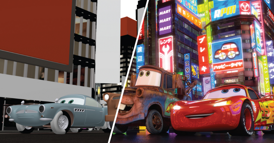
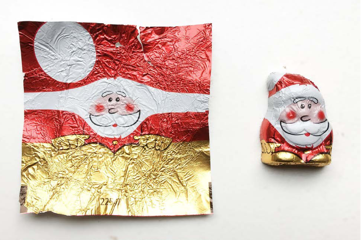
There two ways:
- Subdivide a geometric element in smaller elements
- Each small element has its own colour and shading properties across the surface
- Define a spatial-varying function over the surface of the geometric element
- This function describes variations in (shading) properties
Intuitively, the detail in shading is defined at a higher resolution than the geometric detail.
2D Texture Mapping
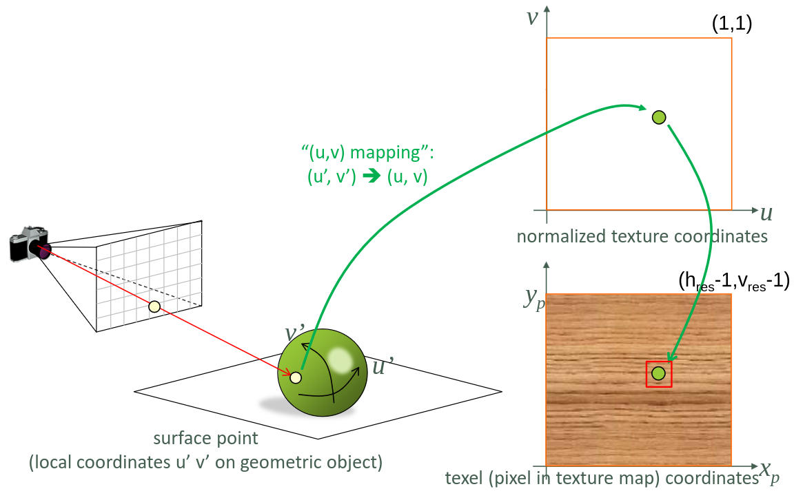
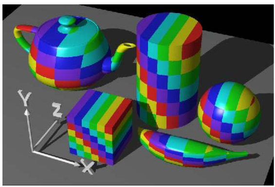
2D texture mapping is taking a 2D image and mapping it onto the surface of a 3D object.
This is done by shooting a ray at the object we want to texture. This gives us local coordinates \(u'\) and \(v'\) on the geometric object. We then apply a (u,v) mapping on these coordinates which gives us normalized texture coordinates which range from 0 to 1. When we have the pixel coordinates for the given surface point, we can extract the pixel colour from the image and use it for shading the point. (\(h_\text{res}\) and \(v_\text{res}\) are the texture image its horizontal and vertical dimensions respectively)
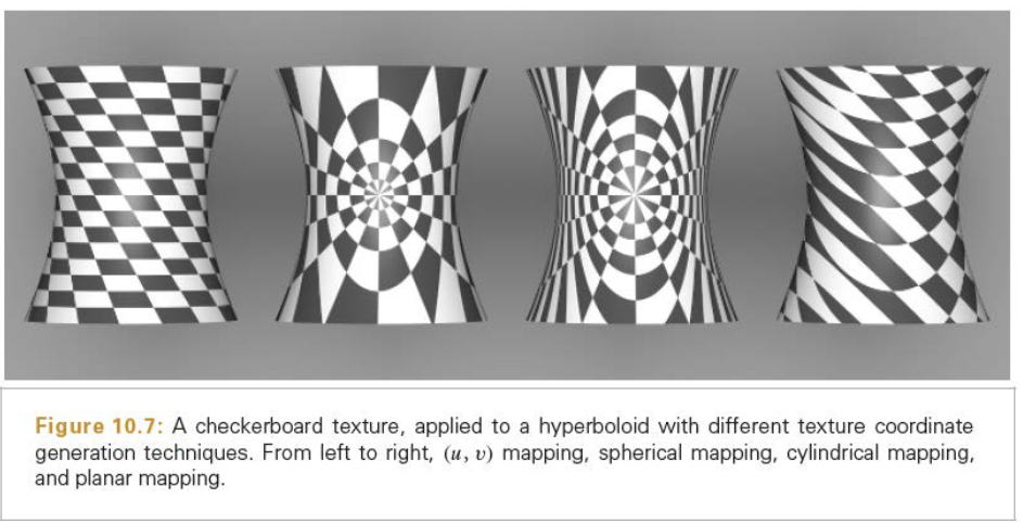
Different (u,v) mappings define different projections of texture on the geometric object.
Cylindrical Mapping
Cylindrical mapping is mapping a texture image onto a cylinder. If the hit point has coordinates (x,y,z), the formula for the azimuth angle \(\phi\) is given by:
\[\phi = \tan^{-1}(\frac{x}{z})\]The (u,v) parameters are then
\[u = \frac{\phi}{2\pi}\] \[v = \frac{y+1}{2}\]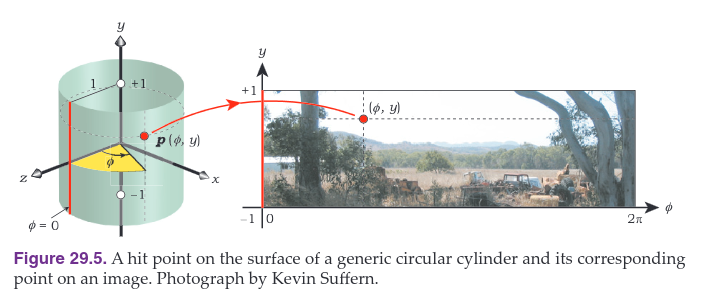
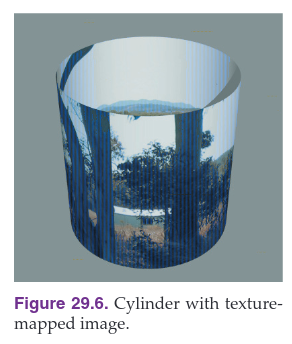
Note that there is a discontinuity across the \(\phi = 0\) line, in the middle of a tree trunk.
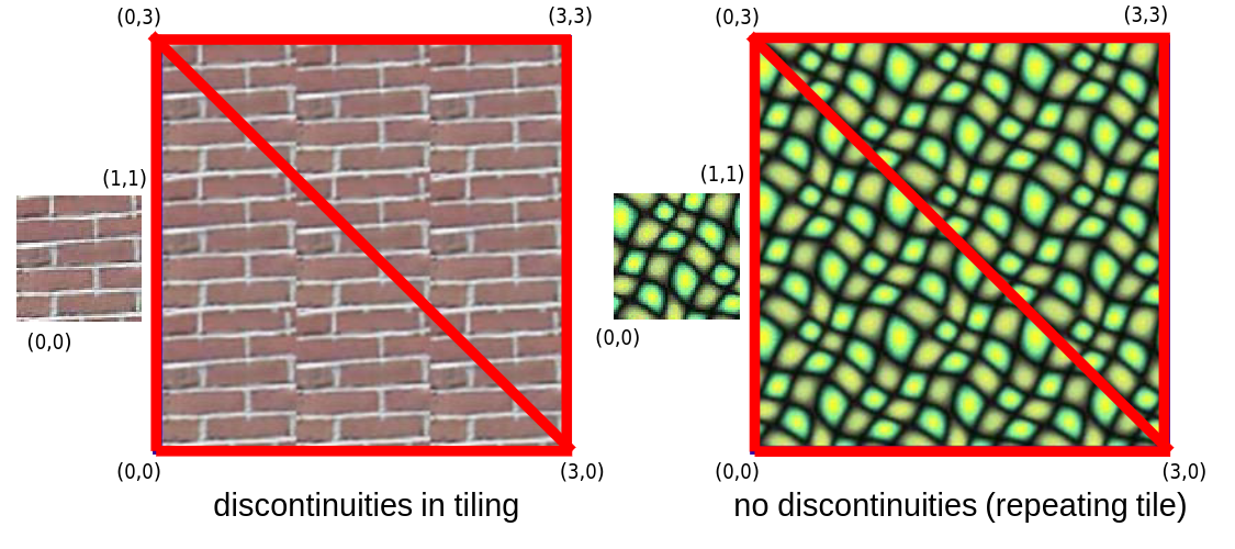
If we want to map an image onto a cylinder without any visual discontinuities along this line, it muse tile horizontally. This means that the left and right boundaries of the images join seamlessly, like strips of wallpapers.
Spherical Mapping
We can map images onto the surface of a sphere, but unfortunately, spheres are not mathematically flat. If we take an image and map it onto a sphere, it becomes distorted.
Given a hit point on a sphere with coordinates (x,y,z), we need to find the values of \(\phi\) and \(\theta\) where:
\[\begin{align}&x = r \sin \theta \sin \phi \\ &y = r \cos \theta \\ &z = r\sin\theta \cos\phi\end{align}\]with \(r=1\). Because the azimuth angle \(\phi\) is the same as for the cylindrical mapping, this only leaves \(\theta\) to discuss. Solving the second equation, we get:
\[\theta = \cos^{-1}(y)\]We do have to take into account that the fact that \(\theta = 0\) when \(v=1\). The (u,v) parameters are therefore:
\[\begin{align}&u = \frac{\phi}{2\pi} \\ &v = 1 - \frac{\theta}{\pi}\end{align}\]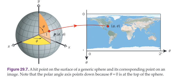
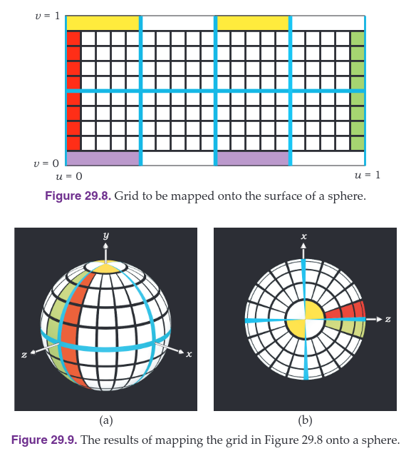
The distortion increases towards the north and south poles of the sphere \((y = \pm 1)\) which can be seen in the figures below, where the lines \(v=0\) and \(v=1\) are compressed to points. Notice how the yellow rectangles have been compressed to small circular quadrants near the north pole.
Planar Mapping
Planar mapping is just holding the to be projected image in from of the object and looking how we need to color each pixel. This is mostly used when we want to texture a big flat surface. Like a wall or floor in architectural visualizations.
Triangle Meshes
For commercial ray tracing, triangle meshes are the most commonly textured objects. In a triangle mesh, every vertex has pre-defined texture coordinates (u,v) that map to a texture space. So every vertex of the 3D model has a corresponding point in the texture image.
On the image below, we can see that the texture coordinates are defined for each vertex of the 3D model on the bottom left. We then look at the texture image to see what colour the corresponding texel has and use that for shading the point.
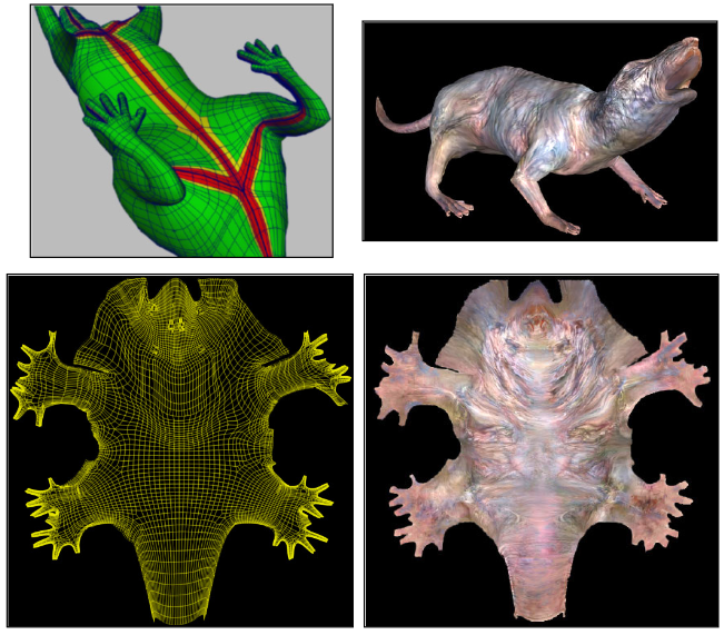
For a point to be shaded within a triangle we interpolate texture coordinates of the vertices (based on barycentric coordinates). This provides a new uv-mapping for texture look-up.
The uv-mapping of the vertices are most often encoded in the 3D model. We can use barycentric interpolation to get the texel coordinated for a given point.
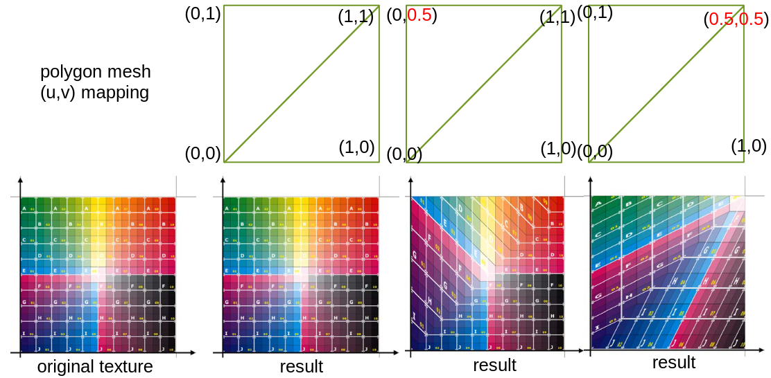
We can adjust the uv-mapping by changing the texture coordinates of the vertices as shown below. In the first image, the texture coordinates and the texture image are the same. In the second image, the y-coordinate of the above triangle is halved, this results in the texture image being shown underneath.
The problem with triangle meshes is that we can get discontinuities in the texture image.
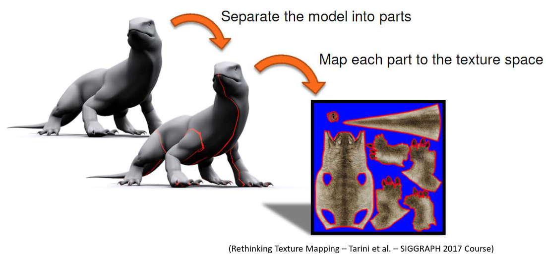
Another problem is that unfolding the 3D model can be difficult and can lead to distortion.
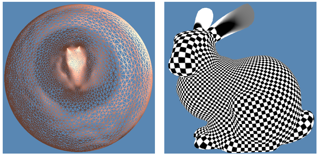
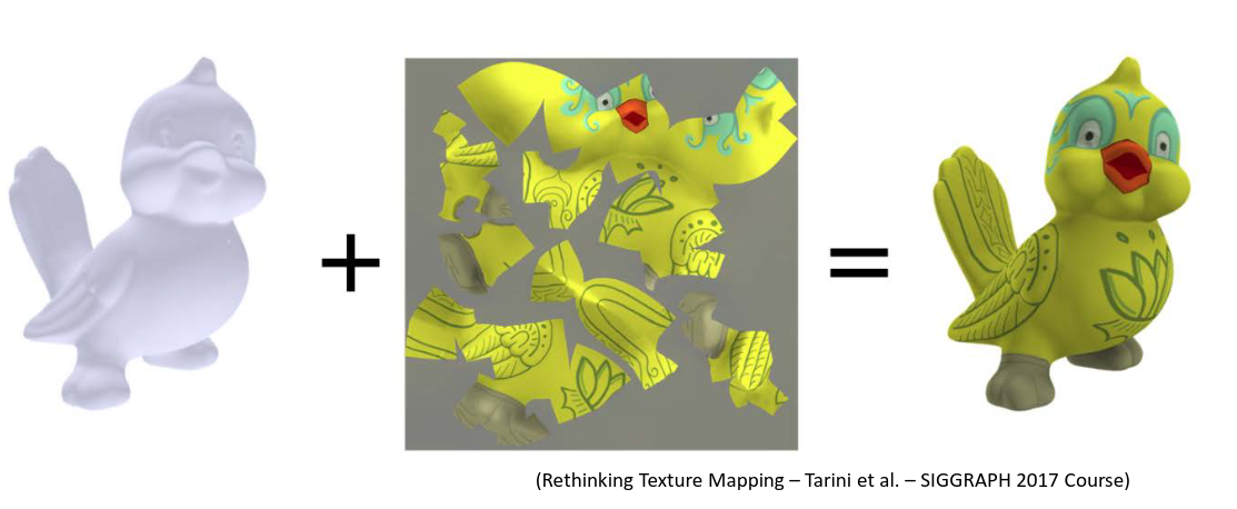
This can be solved by using a texture atlas. A texture atlas is a single texture image that is split into multiple smaller images. This is done by using a 3D modelling program.
Filtering
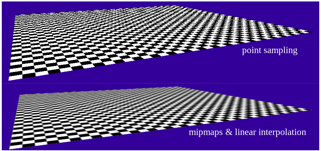
What do we do when there is too much detail in the texture image, which will result in a noisy rendering since we have different texels for a single pixel?
Pre-filtered Textures
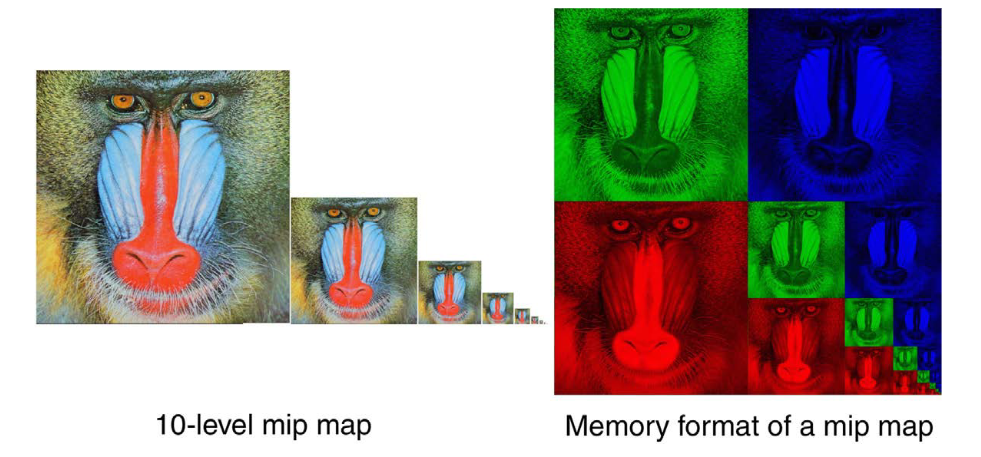
One solution is by using pre-filtered textures, aka MIP mapping. This is done by creating a set of pixel images with decreasing resolution. The smallest image is the original texture image.
Mipmapping is used to optimize the rendering of textures. It does this by creating a sequence of pre-calculated images, each of which is a progressively lower resolution representation of the previous one. The height and width of each image, or level, in the mipmap is a factor of 2 smaller than the previous level.
The purpose is to increase the rendering speed and reduce aliasing artifacts. A high-resolution mipmap image is used for high-density samples, such as for objects close to the camera. Lower- resolution images are used as the object appears farther away. This is a more efficient way of downsampling (minifying) a texture than sampling all texels in the original texture that would contribute to a screen pixel.
The use of mipmaps can improve image quality by reducing aliasing and Moire patterns that would occur at large viewing distances, at the cost of 33% more memory usage per texture.
They are mainly used in real-time 3D rendering, such as in video games, to improve performance.
Bump Textures
Bump textures (also called normal maps) are used to add detail to a surface without actually changing the geometry of the surface. Instead, values from the texture image are used to perturbate the shading normal.
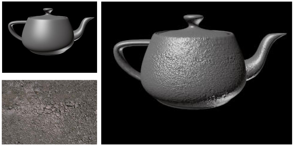
It is done by reading out the values \(\Delta x\) and \(\Delta y\) from the texture map, or by evaluating the ‘bump-function’ \(\Delta x = f(u,v), \Delta y = g(u,v)\).
Then we compute the vectors \(a, b\) to be perpendicular to the normal \(n\) (in the local reference frame). We then compute the shading normal \(n'\) as:
\[n' = \frac{n + \Delta x \cdot a + \Delta y \cdot b}{\|n + \Delta x \cdot a + \Delta y \cdot b\|}\]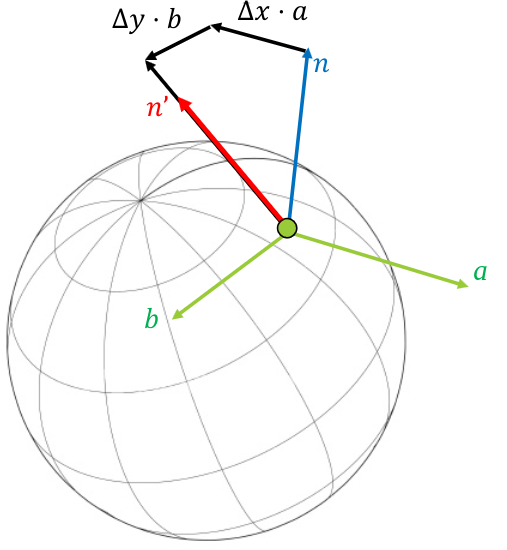
With this method, we can transfer detail from a mesh to a bump map.
Environment Mapping
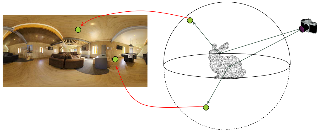
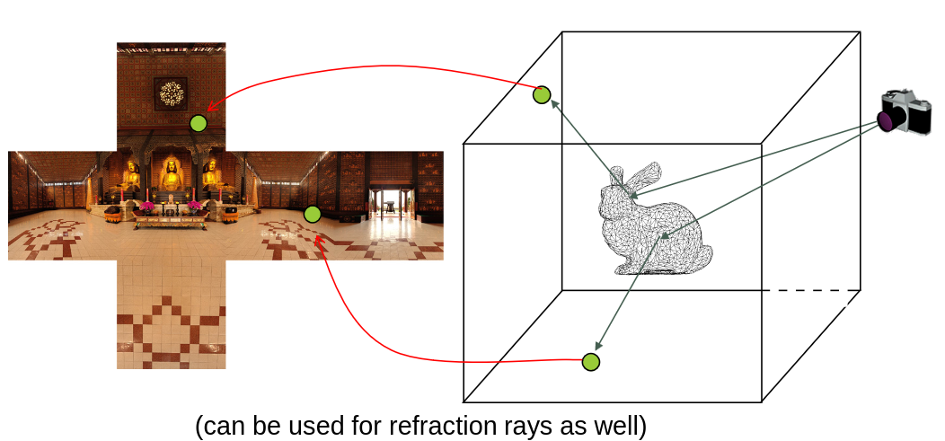
Environment mapping is a technique that allows us to simulate reflections on shiny objects. It is done by:
- Storing the environment to be reflected in a reflection map
- Photograph, or itself rendered from a 3D scene
- Use a perfect reflective direction to access the “reflected color” in the reflection map
- 360 degree camera for photographic acquisition (often in high dynamic range)
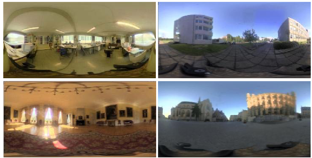
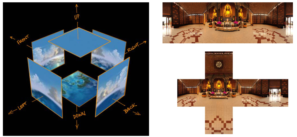
How do we use these reflection maps? We can use them in two ways:
- Pick up the “reflections” from a spherical map:
- Pick up the “reflections” from a cube map
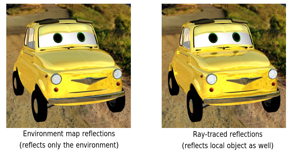
What is the difference between using a environment map and using ray tracing? The difference is that with ray tracing, we get a reflection of every object in the scene, also the ones that we don’t want to reflect.
Procedural Textures
Procedural textures use code to generate colors, instead of extracting them from images. This approach has a number of advantages and disadvantages compared to image-based textures.
\[L = K_a c_r L_\text{ambient} c_\text{ambient} + \frac{k_d}{\pi} c_r L_\text{light} c_\text{light} \cos\theta\]Where \(c_r = F(x,y,z)\) is the function that determines the colour of the surface at that point.
Advantages:
- No mapping is required. Procedural textures can be defined for all points in the world space, a property that allows objects to appear to be carved out of the texture material.
- Procedural textures are compact, with many requiring little to no storage of data.
- Many procedural textures take a number of parameters, a feature that allows a single algorithm or set of related algorithms to generate a variety of related textures.
- Procedural textures don’t suffer the same aliasing problems as stored textures do because they don’t have a fixed resolution.
Disadvantages:
- Although the number of procedural textures is vast, they have all been written by programmers, and the programming has often been difficult.
- Because code has to be executed every time a procedural texture returns a color, they can be slower than stored textures.
Textures & Transformations
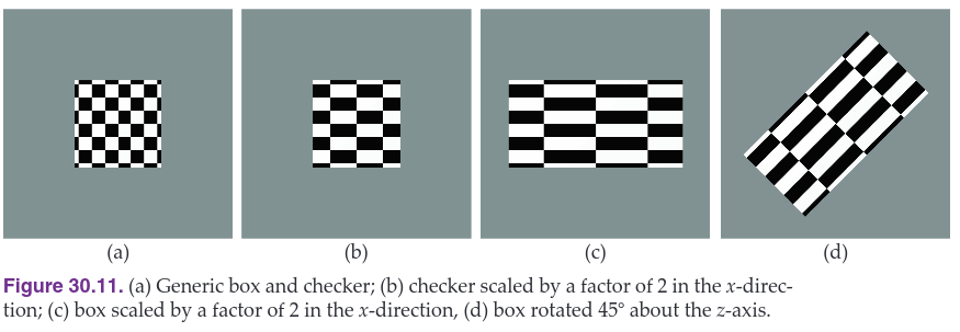
When we scale a sphere, we also want the texture to scale with it:
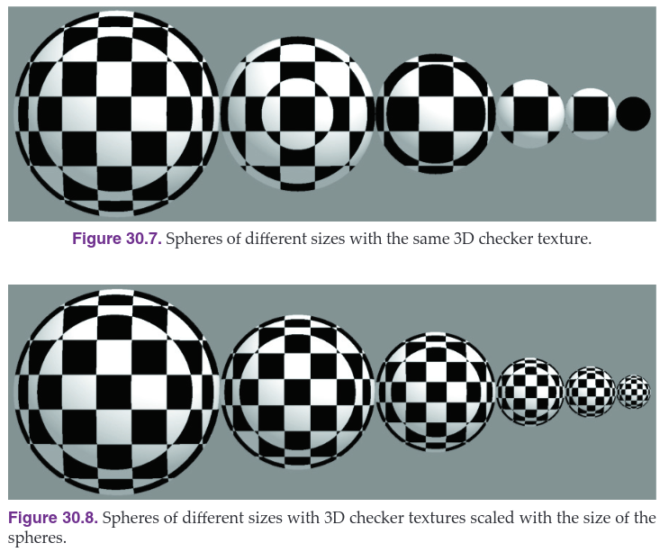
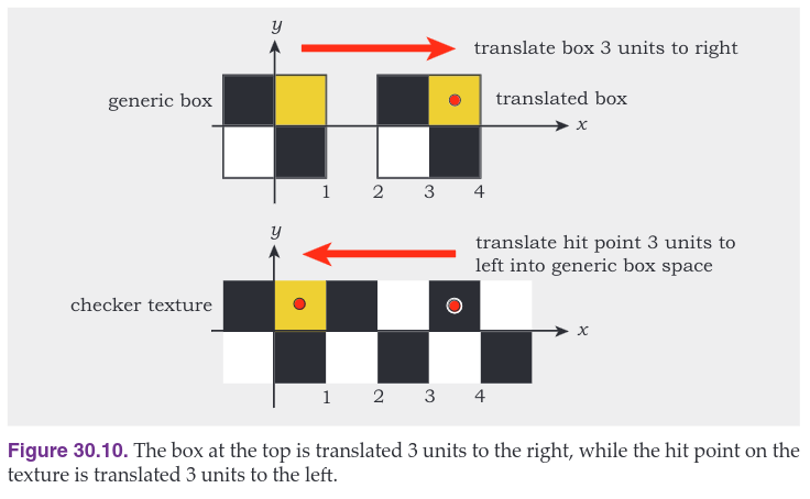
How do we transform the textures? We don’t, we inverse transform the hit point. This is similar to intersecting transformed objects, but here we only have to inverse transform the hit point, not a ray. The image below shows how this is done.
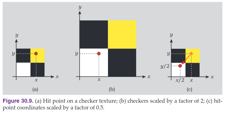
When we transform the object, we also need to transform the texture coordinates. This is done by applying the same transform also to the texture coordinates.
